WEEK 7 & WEEK 8 -
Objective :
(i) To test the spring absorber system
(ii) To test the output from motor ac
Method :
(i) Firstly, by using the motor ac, I test the condition voltage and current.
(ii) With the combination of the rectifier and capacitor, I try to get the output by using DC trainer and try to interface it with the LabVIEW.
(iii) Then, I have to decide the input and output for the DAQ Cards to do some experiment.

figure 1

figure 2

figure 3


figure 4
By this week, I have to build my own absober prototype by using baby swing spring to test the condition motor wether can generate electricity or not.By this week also, I have build rectifier and capacitor circuit that I want to use in my project.Rectifier are function to convert ac to dc and capacitor function as batery to stare an energy .I have use etching method to do this circuit. It takes time to do this because firstly, I have to draw the circuit in software called DIP Trace software. After that, I print the circuit and draw it back to PCB Board. By using the acid, I soak the PCB Board (that I have drawn the circuit) until the colour of the PCB Board turn into light brown. Then, I wash it and let it dried. After that, I put the component (diode) and start to solder it. After my rectifier is complete, the next step is to test the rectifier circuit. In Figure 1, it shown that absober prototype is built and I test it with the rectifier. After the experiment, I can conclude that my absober can produce the output as 12V. Then, I used the DC trainer to interface with the LabVIEW ( as shown in Figure 5 and 6). For the first trial, I get the straight graph for I- V curve. For now, I have to improve to get the correct I-V curve characteristic.
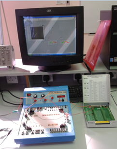
figure 5

figure 6
No comments:
Post a Comment