Thursday, 9 May 2013

Develop Rectifier and Capacitor

WEEK 10


Objective:
(i) To determine output voltage and current
(ii) To create a better result for analysis damping
(iii) To testing the circuit with the my RSA module


Method:
1. Firstly, I have to test the circuit either it can produce the graph or not by using the block that I create.
2. After that, I tried to interface the hardware and software.
3.  Then, by using the same experiment as I do before, I try different type capacitor to see the output produce.

Figure 1

Figure 2

 
Figure 3

A=pinion
B=Rack
C=Rectifier
D=Capacitor


Figure 4


Conclusion :
WEEK 10 - Previously, I did the manual method to determine the voltage and current by using multimeter.
But for this week, it turns out. By this week, a problem occurs when I tried to interface again the software and hardware part.This week also, I have to decide where the suitable capacitor to store the charge and can be using in some equipment.l got a problem because the output does not work and the 
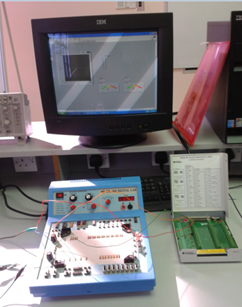
data cannot connect with the hardware part. Figure 1 shown is the block diagram that I have to use in my project. Figure 2 Show that some capacitor and rectifier that I have to use in my project. Inside the block diagram, I use Data Acquisition for current and voltage and the input came from RSA module. From that, it separate into two which is current and voltage. The output from both input, I integrated and connected to graph to see the graph performance. Suddenly, another problem occurs when the DAQ Cards only accept maximum 10V for voltage and 58mA for currents. To solve this problem and suggestion from lab technician, I have use another Rectifier and capacitor to make sure the DAQ Cards can produce the voltage and current that I want.So, I built a new circuit as shown in Figure 3.I has use another rectifier RS406 and capacitor 680uF is aligned in parallel. After that, I tried again to interface it with the software part with a new block diagram. Evidently it worked!
 Further, with the combination of rectifier, capacitor, RSA module and software, the graph is produce. As you can see in Figure 4, the graph is starting to produce I-V curve graph but not exactly. But this success can be proud of after facing some problems. Even though time is running out, I will strive to complete my project. In shaa Allah.


Determine spring constant for my RSA project and real absorber car by using Hooke's Law.

Week 9

For this week based on my adviser opinion I determine spring constant for my RSA project and real absorber by using Hook's Law

HOOKE LAW
Any physicist knows that if an object applies a force to a spring, then the spring applies an equal and opposite force to the object.
Hook’s law gives the force a spring exerts on an object attached to it with the following equation:

F = –kx
Where the minus sign shows that this force is in the opposite direction of the force that’s stretching or
compressing the spring. (k is called the spring constant, which measures how stiff and strong the spring is. x is the distance the spring is stretched or compressed away from its equilibrium or rest position.

RSA SPRING CONSTANT
For my RSA project I using mass of weight of iron (dumbbell) 6.75kg.In real life the acceleration of the gravity is  g = 9.81 m/s2
And the F is determining by mass time gravity of acceleration. How I determine the spring constant for my RSA spring:

Force at the maximum compression of 0.2 meters

F = mg = (6.75kg)(9.8 m/s2) = 66.15 N

Hook’s law says
F = –kx


Looking only at the magnitudes and therefore omitting the negative sign get

k=F/x
k=66.15N/0.2m=330.7N/m
 

This data are very important to make me analysis the project to  make the comparison to the real absorber car.From this data I can find out the input power based on spring constant, This input power I will explain more detail soon.Figure 1 is the weight and figure to how i using that weight to determine spring constant.

Figure 1

 
Figure 2

REAL CAR ABSORBER
I make some example comparison for the spring constant for the actual car that have a mass of 1,000 kilograms,
and have four shock absorbers, each 0.5 meters long determine how strong the spring can be Assuming that shock absorbers use springs,
Each one has to support a mass of at least 250 kilograms, which weighs the following:

F = mg = (250 kg) (9.8 m/s2) = 2,450 N

Where F equals force, m equals the mass of the object, and g equals the acceleration due to gravity, 9.8 meters per second2.
The spring in the shock absorber will, at a minimum, have 2,450 Newton of force at the maximum compression of 0.5 meters.
So the spring constant can be determine 

k=F/x
k=2,450N/0.5m=4900N/m

Figure 3=Real spring absorber car
Figure  3


Tuesday, 7 May 2013

Upgrading the absorber & Testing with the Rectifier and Capacitor Circuit


WEEK 7 & WEEK 8 -
Objective :
(i) To test the spring absorber system
(ii) To test the output from motor ac

Method :
(i) Firstly, by using the motor ac, I test the condition voltage and current.
(ii) With the combination of the rectifier and capacitor, I try to get the output by using DC trainer and try to interface it with the LabVIEW.
(iii) Then, I have to decide the input and output for the DAQ Cards to  do some experiment.


figure 1

figure 2

figure 3


figure 4


 By this week, I have to build my own absober prototype by using baby swing spring  to test the condition motor wether can generate electricity or not.By this week also, I have build rectifier and capacitor circuit that I want to use in my project.Rectifier are function to convert ac to dc and capacitor function as batery to stare an energy .I have use etching method to do this circuit. It takes time to do this because firstly, I have to draw the circuit in software called DIP Trace software. After that, I print the circuit and draw it back to PCB Board. By using the acid, I soak the PCB Board (that I have drawn the circuit) until the colour of the PCB Board turn into light brown. Then, I wash it and let it dried. After that, I put the component (diode) and start to solder it. After my  rectifier is complete, the next step is to test the  rectifier circuit. In Figure 1, it shown that absober prototype is built and I test it with the  rectifier. After the experiment, I can conclude that my absober can produce the output as 12V. Then, I used the DC trainer to interface with the LabVIEW ( as shown in Figure 5 and 6). For the first trial, I get the straight graph for I- V curve. For now, I have to improve to get the correct I-V curve characteristic.

figure 5

figure 6

Wednesday, 17 April 2013

more about labview

Objective :
(i) To complete the LabVIEW program.
(ii) To improve the knowledge about LabBIEW
(iii) To study about LabVIEW database

Method:
(i) Firstly, I do some reserach on LabVIEW on the youtube.
(ii) Then, I try to apply it on the LabVIEW software guiding by technician.
(iii) Next, I try the example given in the LabVIEW software.]


Conclusion:
WEEK 6 - By this week, I tried to figure out how my LabBIEW will look like.This time I try to learn step by step of this software. Firstly, I was introduced the basic system of this software. Shown in Figure 1 is the first page of LabBIEW  where it contain block diagram and front panel. Block diagram is the page where we can put the design for our system for example we put the graph to measure the current/voltage or we can put multimeter to measure the voltage and current. Front multimeter is the place for us to monitor our system. However, during my learning time,error is occur where I can not proceed the next step. It occurs when I tried to pick the voltage in DAQ acquire list, its show that that the wiring connection in DAQ do not appear.So, I have to take another option by using PC in lab. According to Mr.Azman, the LabBIEW that I have installed did not match to the DAQ panel. In addition, he said that LabBIEW software also can interface to the internet like what my project require but I have to study more about it with my advisor. Last but not least, I have to complete my hardware first before I can proceed with the interfacing with the LabBIEW and also internet.

Tuesday, 12 March 2013

install and learn labview

Week 5....
Objective :
(i) To study how to use LabVIEW
(ii) To study the performance of the device 
(iii) To test the LabVIEW 

Method :
(i) First, I have to install the LabVIEW software in my computer (window XP is applicable)
(ii) Then, I have to setup the hardware to make sure it can match with this system.
(iii) Follow the instruction inside.

Result : 


As a conclusion, for this week, I have uploaded the LabVIEW in my laptop. So that, I can learn and started using this software for my FYP. I also get guidance from BMI technician which is Mr. Azman Alias. He will teach me how to use this software more details. I also take an initiative to search by my self at youtube how the connection. http://www.youtube.com/user/Labview# . Figure above shown above is the preview and sample of the LabBIEW. I really hope that my FYP will improve week by week. In Shaa Allah :)

Sunday, 10 March 2013

mechanical project progress

WEEK 4
This week I have been  mechanical work for RSA project.After 3 day working  for this project  as cutting and welding to make spring prototype for  replacing absorber  vehicles.I  was replace the spring vehicle to spring mixer  food (eggs) ,this case to make the reading process easy  when analyzing RSA project soon.there are  some problems such as searching for suitable iron and place.This project are mostly  50done and the process will continue in the next step.for the rack method I using bicycle chain to moved the pinion(freewheel).


figure 1:pinion  component(freewhell) it will be coupled with the motor to generate electricity 

figure 2:my project in 50% coondition to finish

                                                                  figure 3:welding the iron


figure 4:some cutting activity